
The application of different verification methods is a prominent part of the development process for safety related systems. Some methods are suitable for the early lifecycle phases, while others are best used later. In the end, the most significant thing is that all the lifecycle phases can be verified in a sufficient manner and using the method best suited for the purpose. At Mipro, we have found that formal verification increases diversity in order to achieve the best possible verification results and improve the quality and safety of the deliveries.
Using model checking for interlocking software verification
Formal verification in CENELEC signalling standars
The development process for safety critical systems is typically presented in a lifecycle model where the definition of the lifecycle is a straightforward top-down line model or Vmodel or a tailored combination of the two. The principle is easy to understand. The lifecycle starts from the high-level
concept and moves forward to more detailed system definition that considers the risk analysis and requirement specifications, followed by the design and implementation, including all the necessary test phases, and ending with the validated equipment or system. We need to verify all the outcomes from the different lifecycle phases in order to ensure the integrity of the process and the correct operation of the implemented system. This means that verification, as defined in the norms, “is a process of examination followed by a judgment based on evidence that the output items (process, documentation, software or application) of a specific development phase fulfil the requirements of that phase with regard to completeness, correctness and consistency” [1] and as such is a crucial part of the design and implementation process that provides confirmation through examination and objective evidence as to the fact that the requirements have been met.
Given that the functional safety framework presents the lifecycle management model with a lot of requirements, the standards also define a comprehensive list of different techniques and measures for dealing with systemic failures that might be introduced into any lifecycle phase of the development process by human beings. This does not mean that all the presented techniques will be selected, but that a combination of them is required. The adequate combination of the different methods is listed in the tables of techniques and measures depending on the required safety integrity level. These are indicated with letters showing whether the implementation of the method is mandatory (M), highly recommended (HR) or recommended (R). Some methods may also be not recommended (NR). The combination of adequate and suitable techniques typically consists of mandatory and / or highly recommended methods.
One set of techniques involves formal methods. Formal methods are a high-level concept that refers to “mathematically rigorous techniques and tools for the specification, design and verification of software and hardware systems” [1]. The formal methods are not mandatory techniques, but are still highly recommended when the highest safety integrity is required (SIL3 and SIL4). Lower safety integrity levels (SIL1 and SIL2) define these techniques as recommended. The EN 50128
standard refers to several lifecycle phases in software development for the use of formal methods, but does not specify in detail which formal method technique should be used. Instead, the Appendix lists several techniques under the formal method umbrella. In this article, we focus in more detail on how Mipro has used and utilised the formal verification technique. Mipro has selected VTT’s model checking service to support its product development process. The motivation behind this decision to use model checking was an attempt to find a new diverse verification technique to reveal any hidden design issues in reusable software modules and gain fast and easy solution iteration to increase product reliability.
Formal verification results in logical proofs
Formal languages and methods provide a systematic approach to requirement specification and design. Formal methods pave the way for clarity and unambiguity through the use of mathematically rigorous techniques, but also enable formal verification, i.e. logical proof of correctness. Model checking [2] is a formal verification method, where a computer tool called a model checker is used to verify that a formal property holds for a given system model (fig. 1). The result is either a mathematical proof showing that the property always holds or a counter-example, i.e. a model execution path that violates the property. The counter-example can reveal a design issue in the original system or an error made by the analyst when modelling the system or specifying the property meaning that the method is self-correcting.
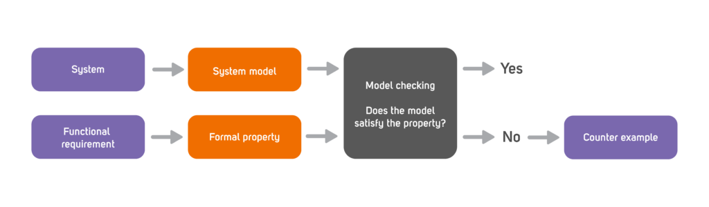
Image 1: In model checking, the analysis is based on the formal specification of functional requirements.
The properties are specified using temporal logic languages such as linear temporal logic (LTL), computational tree logic (CTL), property specification language (PSL) or their different variants. Notably, the properties can also express the absence of any unwanted functionalities (e.g. stating that contradictory or spurious signals/states will never occur). In practice, especially if model checking is applied to designs that have already been subjected to testing, design issues are often revealed though the checks for such “negative” properties. One practical caveat is that the property specification languages do not resemble the other languages commonly used in I&C engineering. The attempts to develop user-friendly (often graphic) languages have struggled to find a reasonable trade-off between expressiveness and ease of use. Languages like LTL are hard to master, but the self-correcting nature of the method assists the analyst in arriving at the correct formulation of each property.
The iterative and cooperative verification process
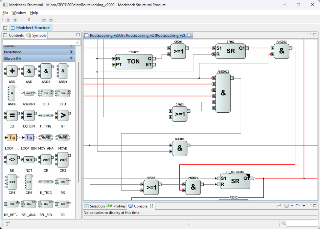
Image 2: MODCHK is a graphic tool for the verification of function block diagrams.
VTT has applied model checking to practical projects since 2008, mostly in the Finnish nuclear industry, where tens of design issues have been detected in different new-build and I&C renewal projects [3]. To that end, VTT and the Fortum energy company have developed a graphic tool called MODCHK (image 2) for verifying I&C logics. Serving as the frontend for the NuSMV and nuXmv model checkers (developed by Fondazione Bruno Kessler in Italy), MODCHK supports a user-friendly analysis of function block diagrams. For example, MODCHK visualizes the counter-examples by animating the block diagram. The elementary function blocks are modeled manually, allowing the analysis of non-standard, vendor-specific block diagrams (common in nuclear applications) in addition to standard IEC 61131-3 logic. Hierarchical logics can be constructed by modeling composite function block types.
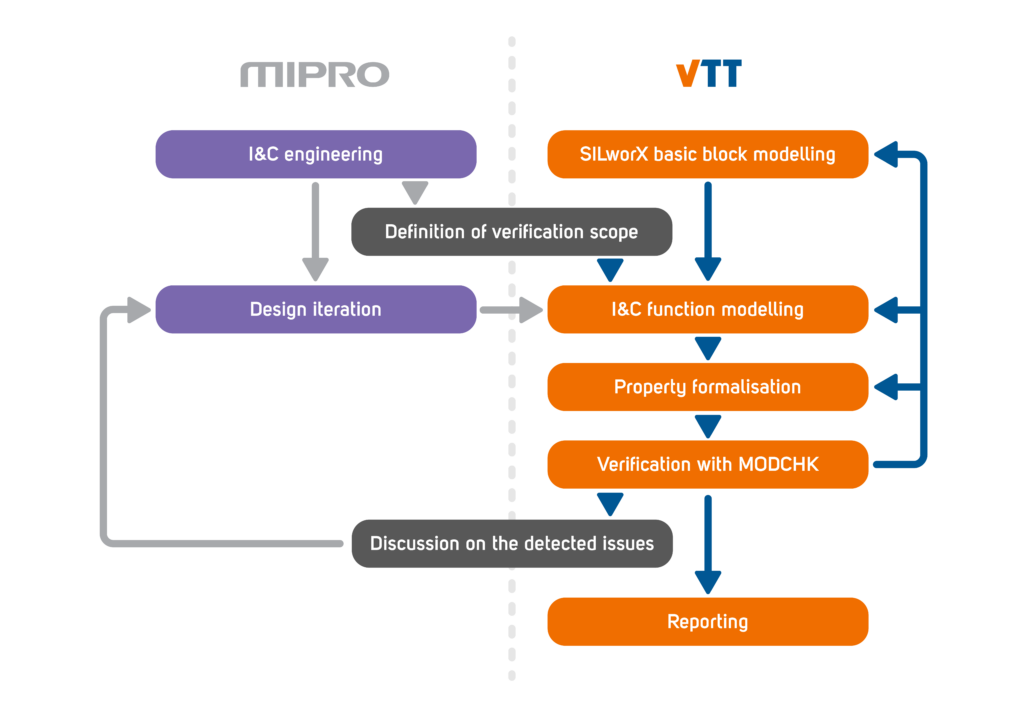
Image 3: The iterative work process between Mipro and VTT
VTT creates models using MODCHK in its projects for Mipro with SILworX block diagrams as the reference. VTT then writes the formal properties based on the requirement specification documents authored by Mipro using natural language. Given that the counter-example can reveal an error that the analyst has made in specifying the logic of a basic function block, drawing the block diagram or specifying the formal properties, the process is iterated until all the properties hold or a counter-example demonstrates a potentially relevant design issue (image 3).
VTT then reports the detected issues to Mipro so that the Mipro experts can analyze their safety significance. If the Mipro designers suggest changes to the logic or the specifications, the corresponding changes can be quickly replicated in MODCHK, and the re-verification is then very fast. Ideally, model checking would, of course, be directly integrated into the designers’ tools.
The application of model checking at Mipro
The functions verified by VTT are part of Mipro’s TCS-O interlocking software, a generic application developed for Finnish railway signaling projects. It includes the core functions responsible for the train route and track geometry and the Object Controller (OC) responsible for controlling the points. (See fig. 4 for an overall view of the software architecture.) Model checking has been applied to the most complex software components. Model checking has proven very useful, as it is hard to achieve full coverage with more conventional testing and verification activities. To date, VTT has found several possible weaknesses and inconsistencies in the application logics. Recurring features in the detected issues include aspects not necessarily accounted for in testing, e.g.:
– A fault or a reset occurs while the points are being set.
– The programmable logic controller (PLC) goes offline and then restarts.
– Different signal changes happen on the exact same PLC cycle.
– The direction commands change back-and-forth very rapidly.
– The expected feedback from a related system does not arrive within the expected time.
– The points are moved to another position manually.
The findings have not been critical to safety, but could have resulted in unwanted momentary system behavior. Based on these findings, Mipro has been able to improve the quality and reliability of the software, simplify the complex logic structures, and thereby reduce the control application’s memory consumption and cycle time.
The quality of the software requirements has also improved during the model checking process. The requirements are now more precise and describe more explicitly the kinds of situations the software is required to never end up in.
The initial construction of the model and the formalization of the properties required a lot of work, but it subsequently became fast and easy to keep the model up to date with changes in software design later in the design iteration. When Mipro proposed changes, VTT re-verified the models to ensure that the changes caused no unexpected errors. Overall, automated regression testing and verification tools like model checking are excellent ways to achieve and maintain safe and reliable software during every lifecycle phase of the system.
A practical example of a detected issue
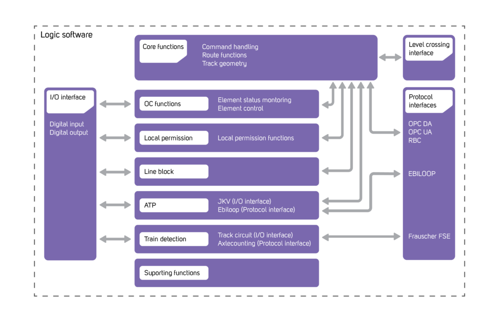
Image 4: An overall view of Mipro’s TCS-O interlocking software architecture
Image 4 depicts a simplified example of a design issue revealed in Mipro’s systems. The example comes from the route setting logic for a set of points, and the intended function is to lock the points at either end position (A or B) once the requested position has been reached. If requests to both end positions A and B are active at the same time, the points will be locked in their current position. When the conflict is resolved, the points will then be allowed to automatically move to the requested position. The latter requirement can be formalized (for position A) in LTL by stating:
G ( (At_A & Request_to_A & Request_to_B)
& X (At_A & ! Request_to_A & Request_to_B)
-> X ! Lock )
In other words, it will always (G) hold that if the points are in end position A, both requests are active, and the request to A is reset in the next state (X), then the lock will be reset.
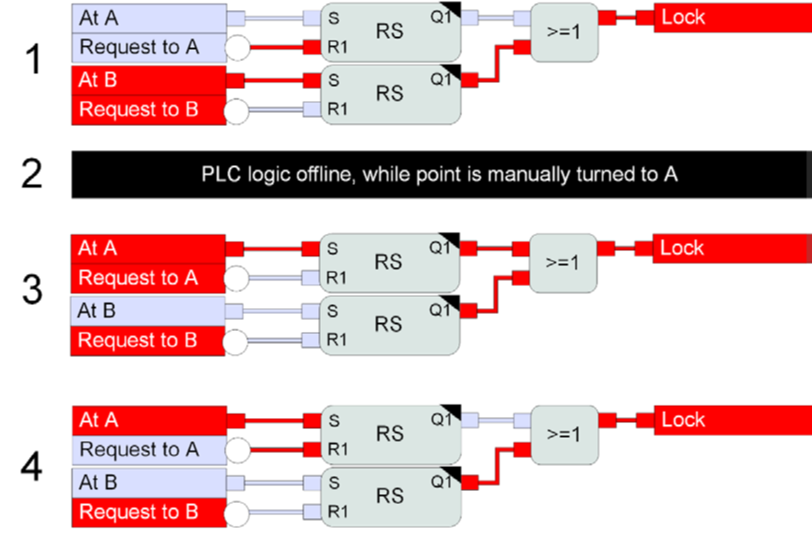
Image 5: A practical design issue revealed by model checking
The model checker returned the counter-example depicted in image 5. We begin in state 1, where the points are locked in the requested end position B. The PLC then goes offline in state 2 for some reason. While the PLC is offline, the points are manually moved to the other end position A. The PLC is then restarted in state 3. Since the SILworX RS memory function block is of a specific ”retain” type (indicated by the black corner triangle), the initial state of the ”B” memory is recalled from when the PLC was last running. Therefore, in state 4, the points remain locked in position A, even though the request to move to B is the only active command.
We have only shown three function blocks here, but the original model was large consisting of 143 inputs, 244 outputs, and a total of 788 function blocks in a diagram that made use of six composite block types. Due to the size of the model, VTT used a technique called bounded model checking (BMC), thereby allowing NuSMV to disprove the property and generate the counter-example in just six seconds (recorded on an Intel i5-1235U running at 1.30 GHz).
The counter-example is representative of the kinds of issues often found with model checking, as it requires something very improbable and counterintuitive to take place. When specifying test cases, such a sequence of events may not come to mind or even necessarily be that easy to replicate in a test suite. With model checking, it is sufficient to formalize the functional requirement and let the algorithms find the counter-example.
Sources
[1] Europäische Norm EN 50128:2011, Bahnanwendungen – Telekommunikationstechnik, Signaltechnik und Datenverarbeitungssysteme – Software für Eisenbahnsteuerungs- und Überwachungssysteme
[2] Clarke, E.; Grumber, O.; Peled, D.: Model Checking. Cambridge, Massachusetts, US: MIT press, 1999
[3] Pakonen, A.; Buzhinsky, I.; Björkman, K.: „Model checking reveals design issues leading to spurious actuation of nuclear instrumentation and control systems“, Reliability Engineering & System Safety, vol. 205, 107237, 2021. https://doi.org/10.1016/j.ress.2020.107237
RELATED CONTENT
authors

Antti Pakonen
Senior Scientist, Project Manager
VTT
Antti Pakonen studies topics related to information technology in industrial automation at VTT. He has been applying model checking in practical projects for over fifteen years, as clients for e.g. Fortum, TVO and STUK, and from 2020 also Mipro.

Juha Turunen
Safety Manager
Mipro Oy
Juha has more than ten years of experience in the field of functional safety as well as overall safety in SMEs and in international cooperation projects. In addition to the ERA partnership, he is a member of the board of the Automation Safety & Security Forum (ASAF) of the Finnish Society of Automation, two committees of SESKO and working groups for the development of standards. SESKO is the National Electrotechnical Standardization Organization of Finland. At Mipro, Juha works as a Safety Manager, responsible for ensuring Mipro’s overall safety.